#include <avr/sleep.h>
#include <avr/interrupt.h> // needed for the additional interrupt
// Routines to set and clear bits (used in the sleep code)
#define cbi(sfr, bit) (_SFR_BYTE(sfr) &= ~_BV(bit))
#define sbi(sfr, bit) (_SFR_BYTE(sfr) |= _BV(bit))
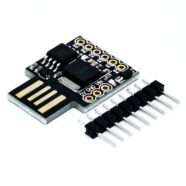
#define led_pin 3
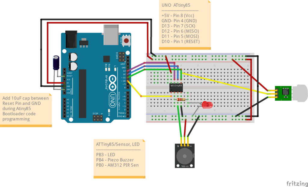
#define PIR_sense 0
#define Buzzer 4
// Interrupt handlers
ISR(PCINT0_vect){ // PB0 pin button interrupt
}
void system_sleep() {
cbi(ADCSRA,ADEN); // switch Analog to Digitalconverter OFF
set_sleep_mode(SLEEP_MODE_PWR_DOWN); // sleep mode is set here
sleep_enable();
sleep_mode(); // System actually sleeps here
sleep_disable(); // System continues execution here when watchdog timed out
sbi(ADCSRA,ADEN); // switch Analog to Digitalconverter ON
}
void alarm_siren(void);
void setup() {
// put your setup code here, to run once:
PCMSK = 0b00000001; // pin change mask: listen to portb bit 0
GIMSK |= 0b00100000; // enable PCINT interrupt
sei(); // enable all interrupts
pinMode(PIR_sense, INPUT);
pinMode(led_pin, OUTPUT);
pinMode(Buzzer, OUTPUT);
}
void loop() {
// put your main code here, to run repeatedly:
if(digitalRead(PIR_sense) == 1)
{
digitalWrite(led_pin, HIGH);
alarm_siren();
//tone(Buzzer, 100, 500);
digitalWrite(led_pin, LOW);
}
system_sleep();
}
void alarm_siren(void)
{
byte i;
for(i=0;i<10;i++)
{
tone(Buzzer, 1000, 100);
delay(100);
tone(Buzzer, 5000, 100);
delay(100);
}
}