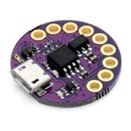
If you want to have an ATtiny85 interrupts tutorial, this is a good place to start.
Introduction
Previously, you’ve learned how to use a basic timer and ADC on your ATtiny85. However, those use cases did not use interrupts. Here you’ll have a basic ATTiny85 interrupts tutorial.
Interrupts are a good way to structure your program execution. You may be missing a lot if you don’t use interrupts. Imagine trying to code using only your peripherals’ flags as signals so that you know their statuses. You would probably find many polling loops inside your code making your code inefficient.
By using interrupts, you not only make your code efficient, but you also make your system more responsive. Interrupts can interrupt program execution at any moment, catching your peripheral events as soon as they happen.
HOw to use Interrupts on an ATTin85
First, configure and set up your peripherals. Note that some peripherals may need special configurations or trigger sources to satisfy your interrupt-driven result. The code examples below will better illustrate this.
Next, enable the interrupt capability of your peripherals. Below, you’ll see two examples of this.
ADCSRA |= (1<<ADIE); // Enable ADC Interrupt
An example of turning on the interrupt of the ADC through the ADCSRA (ADC status and control) register.
TIMSK |= (1<<TOIE1); // enable timer ovf interrupt
An example of turning on the interrupt for a Timer (Timer 1) through the TIMSK (Timer/Counter Interrupt Mask) register.
After that, add an interrupt service routine function in your code. This chunk of code is often usually called an ISR. Note that you must know your peripheral’s specific interrupt vector name for this (here is a table of the entries you can choose from). When an interrupt happens, your program counter (PC) will be able to jump to the address of your ISR thanks to this interrupt vector.
					ISR(ADC_vect)
{
  adc_flag = 1;
}
Here is an ISR for your ADC that simply raises a flag.
					ISR(TIMER1_OVF_vect)
{
  // this is your event
  toggle ^= 1;
  digitalWrite(0, toggle);
}
Here is an ISR for a timer overflow condition on Timer 1 which toggles an LED.
After enabling your interrupts, don’t forget to enable global interrupt functionality by invoking sei() (Set Enable Interrupts).
					  // enable global interrupt
  sei();
Usually, after your peripheral interrupt occurs, there is no need to clear the peripheral’s interrupt flag since it will automatically be cleared if you enable its interrupt functionality.
Example Codes
Timer Overflow Event Using an Interrupt
					#include <avr/interrupt.h>
#include <avr/io.h>

volatile uint8_t toggle;

void setup() {
  // put your setup code here, to run once:
  pinMode(0, OUTPUT);


  TCCR1 = 0x00;                  // normal mode counter

  TCCR1 |= (1<<CS13)|(1<<CS12)|(1<<CS11)|(0<<CS10);
                                // Divide by 8192
                                // Prescaler
                                // CLK=8MHz --> 1sec T1 CLK


  // enable timer ovf interrupt
  TIMSK |= (1<<TOIE1);

  TCNT0 = 0;                      // reset counter

  // enable global interrupt
  sei();

}

// timer0 ovf ISR
ISR(TIMER1_OVF_vect)
{
  // this is your event
  toggle ^= 1;
  digitalWrite(0, toggle);
}

void loop() {
  // put your main code here, to run repeatedly:

}
Above is an example using the Timer1 Overflow interrupt. On setup, the TCCR1 (Timer/Counter1 Control register) is set in normal counter mode along with a prescaler of 8192. If you set the clock of your ATTiny to 8MHz, you should be able to get an interrupt every second. Timer1 overflow interrupt is enabled through TOIE1 in the TIMSK (Timer/Counter Interrupt Mask) register. Next, global interrupt is enabled by invoking sei().
Once a Timer1 overflow commences, the code in the ISR(TIMER1_OVF_vect) should execute. Here, the ISR code simply toggles an LED every second.
ADC Conversion finished Interrupt
					#include <avr/interrupt.h>
#include <avr/io.h>
#include <SendOnlySoftwareSerial.h>


uint16_t adc_value;
volatile uint8_t display_flag;

SendOnlySoftwareSerial Monitor (0);  // use

ISR(ADC_vect)
{
  display_flag = 1;
}

void setup() {
  // put your setup code here, to run once:

  // Start the Software Serial Monitor
  Monitor.begin(9600);

  adc_setup();

  sei();  // Set Global Interrupt ON
}

void loop() {

  if(display_flag)
  {
    adc_value = ADCL|(ADCH << 8);                 // ADC value is left justified. Use operand precedence rules
                                                    // left to right precedence, so ADCL is read first
    Monitor.print("10-bit ADC");
    Monitor.print(" value is: ");
    Monitor.println(adc_value);

    display_flag = 0;
  }
}


void adc_setup()
{
  // disable digital input
  DIDR0 |= (1<<ADC0D)|(1<<ADC2D)|(1<<ADC3D)|(1<<ADC1D);

  // ADC Left Shift Result
  ADMUX |= (1<<ADLAR)|

  // ADC Voltage Referrence
            (0<<REFS2)|(0<<REFS1)|(0<<REFS0)|        // Vcc is used as Voltage Referrence


  // ADC Input Channel/s
            (0<<MUX3)|(0<<MUX2)|(1<<MUX1)|(0<<MUX0);   // Use ADC2 on pin PB4 as ADC input

  // ADC Trigger
  ADCSRB |= (0<<ADTS2)|(0<<ADTS1)|(0<<ADTS0);       // Free Running Mode

  // ADC clock prescaler
  ADCSRA |= (0<<ADPS2)|(1<<ADPS1)|(1<<ADPS0)|       // Use a divide by 8 Prescaler.
                                                    // Sysclock = 8MHz, ADCclk = 1MHz (max)

            (1<<ADATE)|                             // ADC Auto Trigger Enable

            (1<<ADIE)|                              // Enable ADC Interrupt

            (1<<ADEN)|                              // Enable the ADC

            (1<<ADSC);                              // Start ADC Conversion

}
As in the previous blog about using the ADC on the ATTiny, this example uses the SendOnlySoftwareSerial library to display the ADC results. Here, the variables declared are adc_value to hold the ADC value and display_flag to display the ADC values correctly on the software-based serial port.
On adc_setup(), note the usual setup procedures as before. However, to be able to use the ADC’s interrupt function continuously, a trigger source running a free-running value is used through the ADTSn bits on the ADCSRB (ADC Control & Status Register B).
Similarly, the auto-trigger enable bit (ADATE bit) and the ADC interrupt enable bit (ADIE) are set on the ADSCRA (ADC Control & Status A) register to continuously generate ADC interrupts.
With these settings, you can now start ADC conversion (through ADSC on the ADSCR reg). The first ADC result triggers an interrupt then vectors through the ADC_vect ISR(). Here only a display_flag is set. The display_flag allows main to correctly display the ADC values (note that some ADC values are dropped because of the speed of conversion). After which, continuous ADC conversions commence as this is what you’ve set on your ADC control registers.

