This article shows you how to charge Li-Ion batteries with BMS using a modular DC-DC converter. Get to know the details below.
Introduction
By now, you should know that many portable gadgets use Li-Ion batteries. Maybe you would have wanted to create your own Li-Ion battery charger yourself. It’s relatively easy to do this by just using an off-the-shelf modular DC-DC converter together with a BMS module for safety reasons.
Charging Li-ion Batteries with a DC-DC Buck Converter.
Several DC-DC Converter modules today are flexible in that they can be used in various configurations. These modules can act as constant voltage or current sources. With this, they come with a mode to become battery chargers to. The previous blog, Charge a Li-Ion Battery Using only a DC-DC Converter discussed this process using an off-the-shelf 5A DC-DC Adjustable Step Down CC CV Power Supply Module.
Note that the process above is for charging single-cell Li-Ion batteries. To charge several batteries, it’s recommended to add a BMS for safety reasons.Â
Why USe a BMS (Battery MANAGEMENT System)?
You’ll surely need a BMS if you’re concerned about the safety of your battery charging and discharging setup. Along with this, you’ll need a way to determine whether each of your batteries or battery packs are already fully charged or about to be drained. The BMS’ function is to cut off the batteries from the charging source or load when the said situation happens. This lengthens the lifespan of the batteries as well as prevents them from catching fire. The BMS can also protect your battery in case of a short-circuited load if the BMS has this capability.
BMSs’ are specified in terms of how many and what kind of cells they can monitor as well as their maximum voltage and discharge rate. For example, a 4S 18650 40A Li-Ion BMS can handle four 18650 Li-Ion cells in series (or series-parallel – for higher currents) and can handle maximum loads of up to 40A. The BMSs’ spec sheet should specify the maximum charge current they can handle.
How to Connect the DC-DC Converter, BMS, Battery, and Load Altogether.
Below is a typical DC-DC converter, BMS, Li-Ion Batteries, and load connection setup.
As you can see, the cells are in series (3S type), giving a total output voltage of approximately 12V (3.6V – 4.2V per cell ~ 10.8 – 12.6V total). You have the option to have parallel cell connections to increase the current capacity. The end positive and negative terminals of the batteries connect to the 12.6V and 0V terminals respectively.
Necessary tap points are needed for each node of your battery pack. This ensures each battery voltage is monitored. This also makes the battery balancing function run in case your BMS supports this feature. Above, these nodes are 0V, 4.2V, 8.4V, and 12.6V.
A load is connected across the power terminals (+) and (-). These same terminals also connect to the DC-DC converter charger module so that you can charge your batteries. With this type of connection, it’s best to switch off your load while charging to have adequate charging current reaching your batteries.Â
Demo of Battery Charging with a BMS
Below is a typical charging session demo using a 19V laptop charger, a DC-DC buck converter (5A DC-DC Adjustable Step Down CC CV), a 16.8V (4S) 30A BMS module, and four pieces of 2500mAH Li-ion batteries.
First, make sure your battery voltages are close to one another.
It’s best to keep individual battery voltages close to one another. This scenario is more important if your BMS does not have a battery balance feature. You wouldn’t want your charging session terminated early because a single cell has fully charged while the others have not. Similarly, while using your battery pack, you wouldn’t want the pack cut-off because one cell has depleted to under-voltage levels.
Connection Setup
Below is a typical connection setup of a laptop charging adapter, a DC-DC buck converter module, a BMS, your Li-ion batteries and load.Â
As you can see the Laptop charger DC output terminals are connected to the input of DC-DC buck converter module.Â
The DC-DC buck converter output terminals are connected to the BMS power terminals P+ and P-. These terminals provide power to the MOSFET transistors of the BMS to be able to charge your Li-ion batteries. As from the previous charging setup, these same terminals are also connected to your load. To charge your batteries faster, it’s best not to use your load while charging.
The (+) and (-) end of the battery pack connects to the B+ and B- terminals of the BMS board, respectively. Aditionally, each battery node connects to points on the BMS. In this example, a special connecting terminal composed of 5 wires does this. These terminals monitor individual battery voltages.
Adjusting the Maximum CHarge Voltage of the DC-DC Converter
Now, cotinue to set the maximum charging voltage of the DC-DC Converter. This can be done by adjusting the voltage adjust pin of the DC-DC to 16.8V (4S = 4.2V * 4).
Adjusting the Maximum Current Limit of the DC-DC Converter
Adjust the maximum current limit of the DC-DC to match the constant charging current. This should be equal to about 1C of your battery capacity (here it is 2500mAH or 2.5A).
Begin with a Constant Current Charge
Here, after partially depleting the batteries (well below the full charge voltage of 16.8V), the charge mode enters constant current mode. At this point, note that the charging current stays at approximately 2.48A (~2.5A) as the charging voltage tries to reach maximum capacity of 16.8V. Also see that the current limit LED and the charging indicator LED is lit during this time.
The Constant Voltage Charge
After constant current, the charging mode switches to constant voltage after it has reached 16.8V. At this point, you must see the current limit indicator go off while the charging indicator is still lit. Notice the current drop slowly during this time. This will continue to drop after some time to a very low value.
CHarge Termination
Charge termination occurs when the current reaches a very small value (reaching 0.1C). However, charge termination can also happen when an “imbalanced” battery voltage is detected (at more than 4.2V) causing the charging sequence to terminate. In both cases, you must see the charging finished indicator light up.
SHOP THIS PROJECT
-
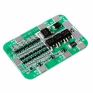
6S 18650 Lithium Battery Protection BMS Board – 22.2V 12A
$16.95Original price was: $16.95.$14.95Current price is: $14.95. Add to cart -
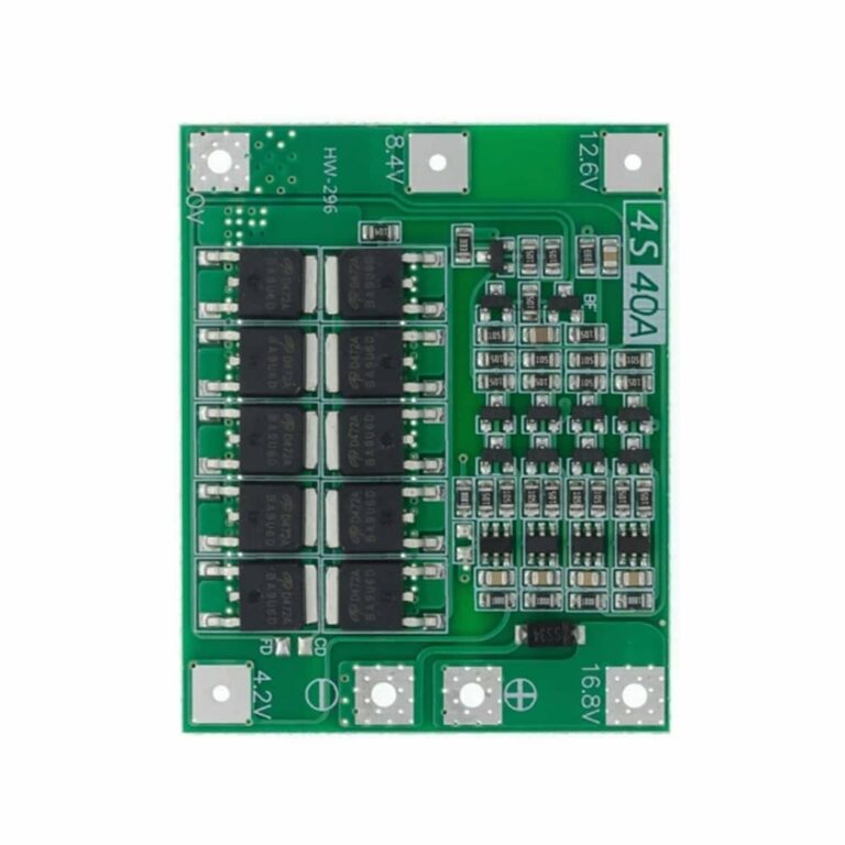
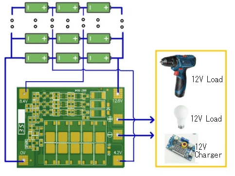
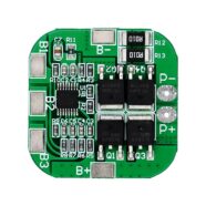
4S Lithium Battery Protection BMS PCM Board – 14.8V 16.8V 20A
$15.95Original price was: $15.95.$14.95Current price is: $14.95. Add to cart -
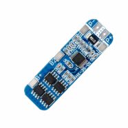
2S 18650 Lithium Battery Protection BMS Board – 7.4V 10A
$15.95Original price was: $15.95.$14.95Current price is: $14.95. Add to cart
SHOP THIS PROJECT
-
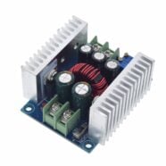
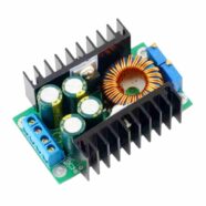
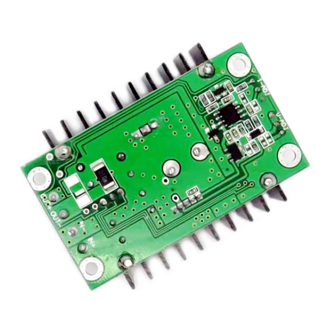
DC-DC 20A 300W Adjustable Step Down Constant Current LED Driver Power Supply
$38.95Original price was: $38.95.$36.95Current price is: $36.95. Read more -
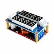
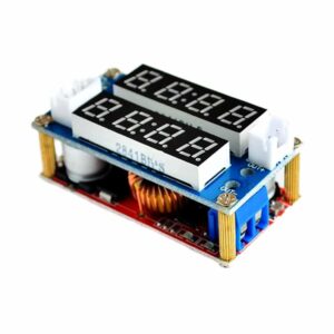
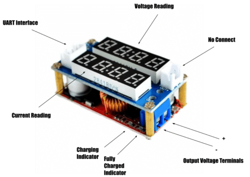
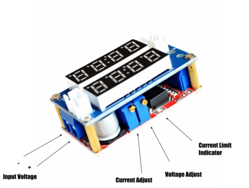
5A DC-DC Adjustable Step Down CC CV Power Supply Module with Voltmeter and Ammeter
$28.95Original price was: $28.95.$27.95Current price is: $27.95. Add to cart