This article continues from learning how to create the base body of your electronic enclosure in FreeCAD.
Introduction
The last article taught you how to create the base body of your electronic enclosure in FreeCAD. This time, you’ll learn how to create corner pillars with screw holes and a pocket on the enclosure base to bind a top cover.
How to Make Pillars and Screw Holes for your Enclosure Cover
1. Create Inside Corner Fillets
To do this, go to wireframe mode through the view icons above. This process will help you pick the inside corners more easily. Then click on all the inside corners while holding the Ctrl key. After that, you can go back to As Is view mode. Now press the chamfer selected edges tool above and pick a size. Here, 8mm is used.
Tip: If you want to move the 3D object to have a better view, simply hold and click the middle scroll button and the left or right mouse button while moving your mouse.
2. Create Screw Holes on the Pillars
Pick the surface where the pillars are and make a new sketch there. Now create circles (with arbitrary radius values for now) that will mark where your screw holes are.
Create edges linked to an external geometry by clicking on its icon above. This process helps in picking points not on the new sketch. Now align the circles to the outside edges of the base body by 4mm.
You can now generate the actual screw holes. Make sure that your screw hole sketch is selected, and then pick the create a hole icon. Choose ISO metric regular profile and choose Threaded. Choose a screw size (M3), then make a depth (15 mm).
3. Create a Pocket for the Cover
A pocket will help your cover snugly fit on your base. With this, create a new sketch on the top surface of your base. Next, create a rectangle. You’d want the edges of this rectangle to have space allowances (at least 0.1mm) for your cover to be inserted successfully. With this, allot 0.9mm space from your pocket to your side edges. Next, create the depth of your pocket to be 4mm.
That’s it!! You’ve created your enclosure base with screw-hole pillars and a pocket. Next, prepare to create your enclosure cover.
HOw to Make your Cover
1. Create a New a Cover Part
You may want a separate assembly document for your enclosure. An Assembly document will help you visualize how your parts come together. With this, you can create a separate FreeCAD part for your cover. Choose File -> New and then save this document as Cover. Next, don’t forget to go to the Part Designer workbench.
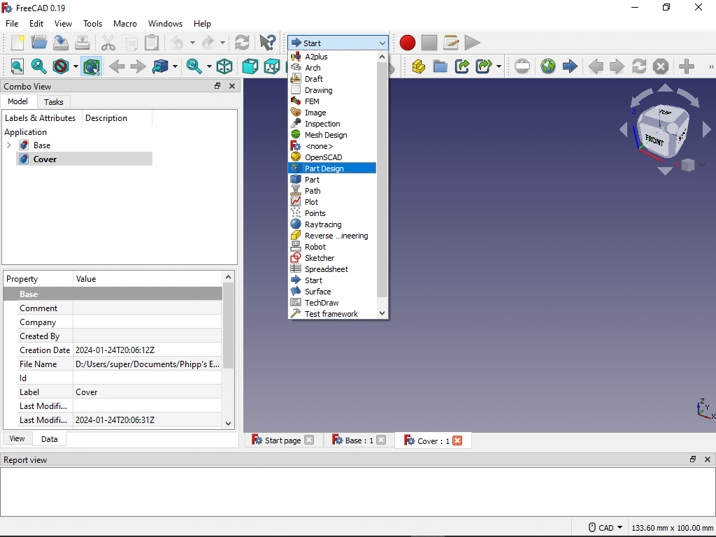
Create a body and start a new sketch for your cover. Next, create a rectangle. The size of your cover depends on the parameters you’ve set up on your base, specifically, the size of your pocket and base edges. Previously, you’ve made a 100mm x 75mm base box with a pocket 0.9mm from the edges. With this, there is an intended space allowance of 0.1mm on the inside edges of your base to the sides of your cover. This space will help you insert your cover to the base comfortably. Your cover should now have a 98mm x 73mm size, indicating a 1mm spacing from the edges of your base box. Pad the sketch to create a 3D view.
2. Create Holes on the Cover
Create a new sketch on the surface of the cover to draw the circles for the mounting holes. Arbitrarily set their radius. Set the distance of the holes to the edges like the distance from the base box minus one since that is what you did to the current edges of your cover. This distance is 3mm.
Make the holes while the sketch is selected. Pick ISO Regular Metric as Profile. Make it threaded. The size is M3, and the depth is Through-All. You can optionally pick a hole cut type like counter-bore or countersink. Here we’ll use none.
You've Just Finished the Cover and Base of your Electronic Enclosure
That’s it! You’ve just learned how to create the pillars, mounting holes, and top cover of your electronic enclosure in FreeCAD. Rotate your electronic enclosure parts to check and verify them! 🙂
The next part will teach you how to assemble or join these parts in an Assembly Workbench.
SHOP THIS PROJECT
-
Digital LCD Thermometer Temperature Gauge with Probe
$15.95Original price was: $15.95.$14.95Current price is: $14.95. Add to cart

