This article continues from the previous blogs about creating an electronic enclosure in FreeCAD. Specifically, it will focus on the FreeCAD A2Plus Workbench in tutorial form.
Introduction
Last time, you created a separate base and cover part. You could have created them on a single FreeCAD document using multiple bodies; however, an assembly view will be generated here instead. An assembly document helps view and manage how your parts form your enclosure. Here, you’ll specifically learn the A2Plus workbench add-on in FreeCAD through a guided tutorial.
Install the A2Plus Assembly Workbench
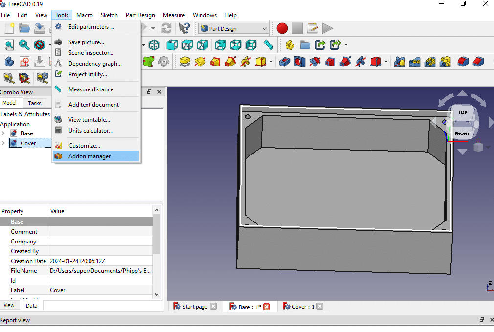
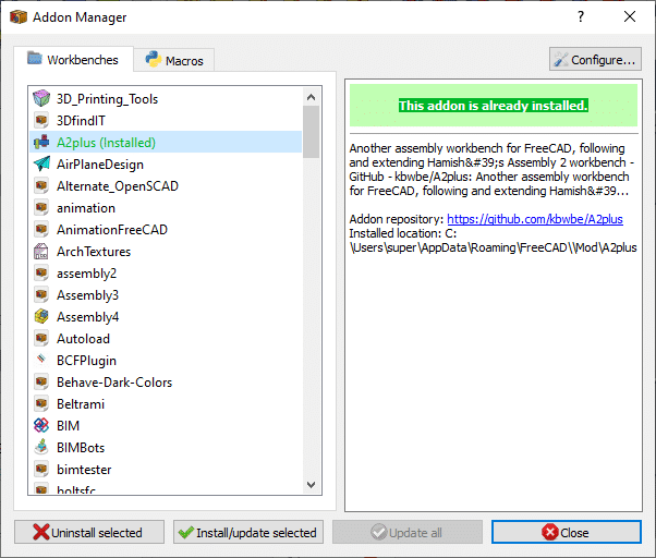
1. Go to Tools –> Addons Manager. Pick A2Plus on the Workbenches tab. Install it.
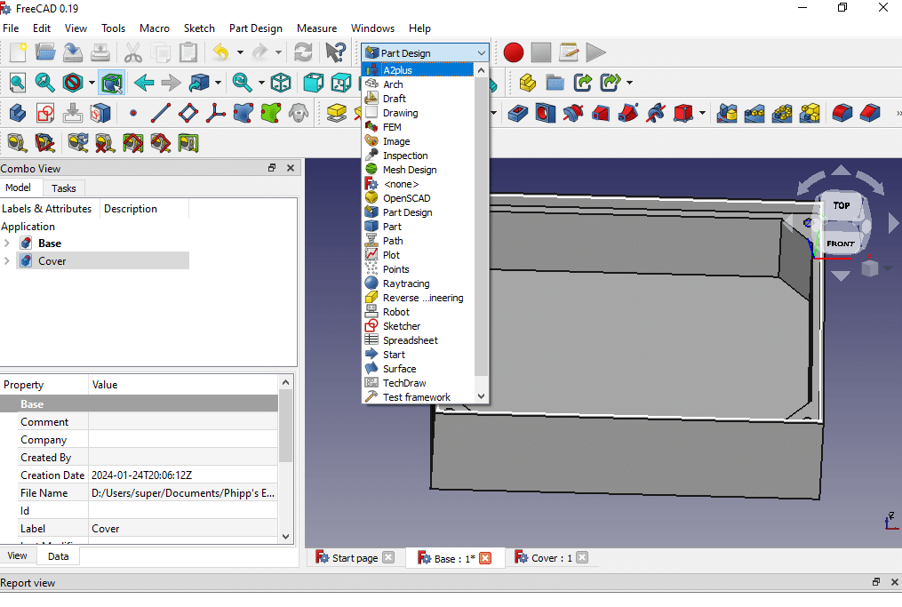
2. You should see the A2Plus Workbench on the drop-down menu after successful installation.
Create your Assembly Document
1. Add all your parts from external files to the assembly. To do this, click the Add External File button above. Drop the parts one after the other on the assembly.
2. Before moving the part, click the surfaces or edges of the base and cover that you want to be aligned. Use the Ctrl key to select the two surfaces. Next, click the Plain Coincident Constraint button above. Insert an offset space between the two bodies. Here, we previously calculated a space of 0.1mm.
You’ll see that the surfaces coincide even though they have not touched each other yet. To see this situation, move the cover part through the moving part under the rule of constraints tool.
3. Pick another pair of surfaces to align the two parts. Don’t forget to add the 0.1mm offset space between them.
4. Pick the cover’s bottom surface and the base pocket’s bottom surface to put the cover in place.
That’s it!! You’ve finally made the assembly details of your electronic enclosure in FreeCAD using the A2Plus assembly workbench. Now you can create any project enclosure following this FreeCAD A2Plus tutorial! Have fun 🙂