					#include <stdio.h>
#include <stdlib.h>
#include <string.h>
#include "freertos/FreeRTOS.h"
#include "freertos/task.h"
#include "soc/soc_caps.h"

#include "esp_adc/adc_oneshot.h"
#include "esp_adc/adc_cali.h"
#include "esp_adc/adc_cali_scheme.h"
					#define MY_ADC_CHANNEL  ADC_CHANNEL_0

static int adc_raw;     // adc raw reading
static int voltage;     // adc raw coverted to voltage
void app_main(void)
{
					    // 1 -- Initialize the ADC
    adc_oneshot_unit_handle_t adc1_handle;
    adc_oneshot_unit_init_cfg_t init_config1 = {
        .unit_id = ADC_UNIT_1,
    };
    adc_oneshot_new_unit(&init_config1, &adc1_handle);
// 2 -- Configure the ADC
adc_oneshot_chan_cfg_t config = {
.bitwidth = ADC_BITWIDTH_DEFAULT,
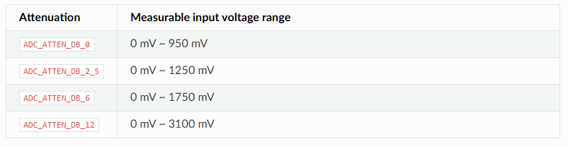
.atten = ADC_ATTEN_DB_12,
};
adc_oneshot_config_channel(adc1_handle, ADC_CHANNEL_0, &config);
					    // 3 -- Calibrate the ADC
    adc_cali_handle_t adc1_cali_chan0_handle = NULL;
    adc_cali_curve_fitting_config_t cali_config = {
        .unit_id = ADC_UNIT_1,
        .chan = ADC_CHANNEL_0,
        .atten = ADC_ATTEN_DB_12,
        .bitwidth = ADC_BITWIDTH_DEFAULT,
    };
    adc_cali_create_scheme_curve_fitting(&cali_config, &adc1_cali_chan0_handle);
while(1)
{
					        // 4 -- Read raw ADC value
        adc_oneshot_read(adc1_handle, ADC_CHANNEL_0, &adc_raw);

        // 5 -- Convert raw to voltage
        adc_cali_raw_to_voltage(adc1_cali_chan0_handle, adc_raw, &voltage);

        printf("ADC Reading is: %dmV\n", voltage);
vTaskDelay(1000/portTICK_PERIOD_MS);
}
// 6 -- Delete Calibration scheme
adc_cali_delete_scheme_curve_fitting(adc1_cali_chan0_handle);
}