Here is an interesting example of STM32 binary semaphores: Fading LEDs in a sequence.
Introduction
Previously, you’ve learned how to use semaphores by fading LEDs in sequence through the LEDC hardware of an ESP32. However, STM32s don’t have this hardware. With this, you’ll have to fade their LEDs using timers (in PWM mode) and use semaphores to specify their sequences. This process is a good place to learn about STM32 binary semaphores and FreeRTOS.
Binary Semaphores
Binary Semaphores were already introduced and discussed in What are Binary Semaphores in FreeRTOS? It states that:
A binary semaphore is like a 1-bit queue used for synchronization purposes. They have practical applications on program flow between tasks. For example, a binary token can be checked to see if a task should continue running statements or block itself for other tasks to run. This token can be given or activated through another task.
Using RTOS and Semaphores in STM32CubeIDE
An overview of using FreeRTOS was discussed in Writing your First RTOS Program using STM32CubeMX. You can use this as reference.
Fading LEDs in Sequence using PWM and Binary Semaphores
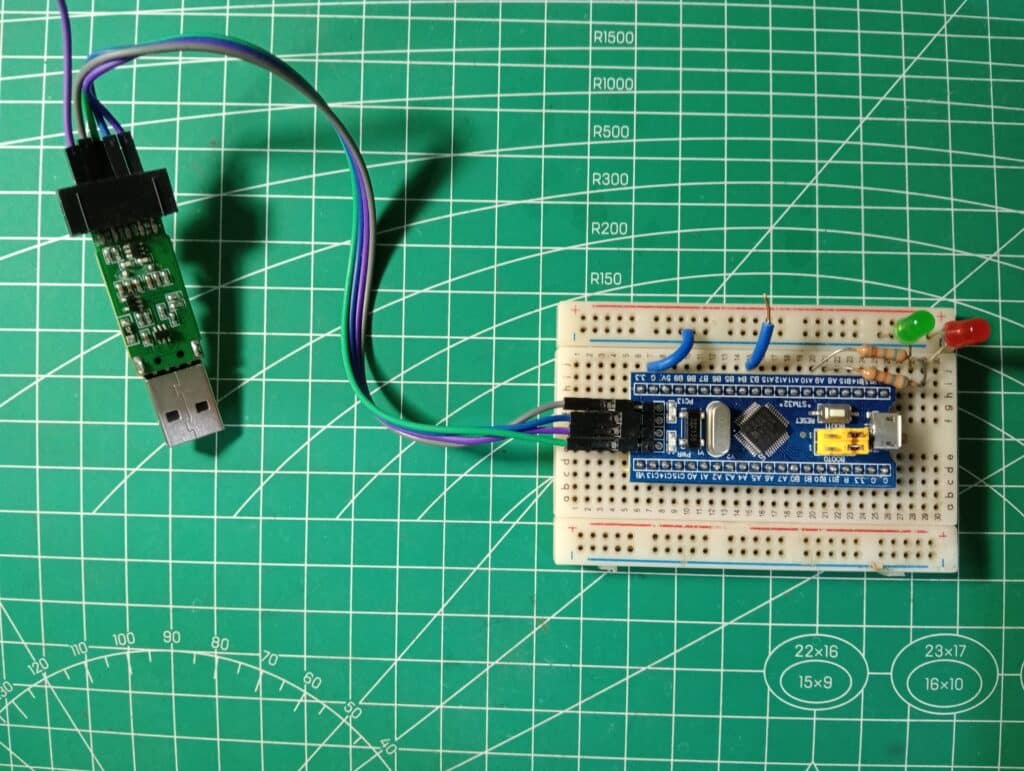
Here, an STM32 BluePill is used to fade LEDs through PWM timers and Binary Semaphores through port A8 and A9.
Fade up and Fade Down of a Single LED
Setup the necessary parameters in STM32CubeIDE to start your BluePill correctly as in Writing your First RTOS Program using STM32CubeMX. The setup includes choosing the correct clock sources, Sys Time Bases, RTOS features etc.
Setting the PWM Timer
As the PWM output is setup using a timer, follow these graphical settings for the timer:
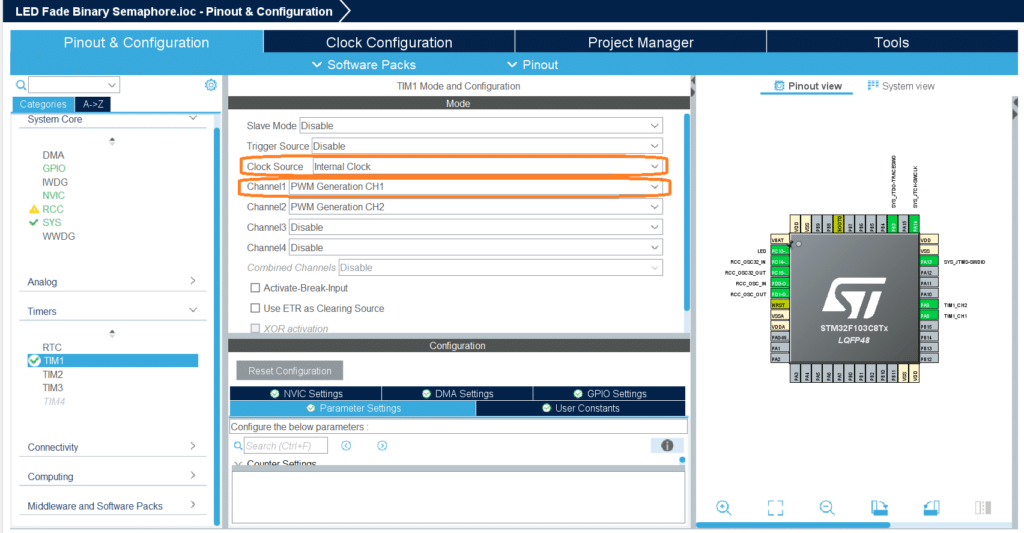
Timer TIM1 is used with a Clock Source of Internal Clock. Channel 1 is used as PWM Generation Output and is in port PA8. We’ll be using Channel 2 in another example.
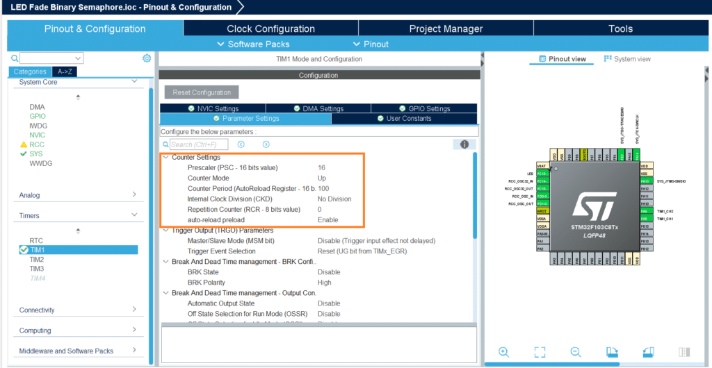
The Counter Settings are chosen with a pre-scale of 16, Counter Period of 100, and auto-reload preload enabled.
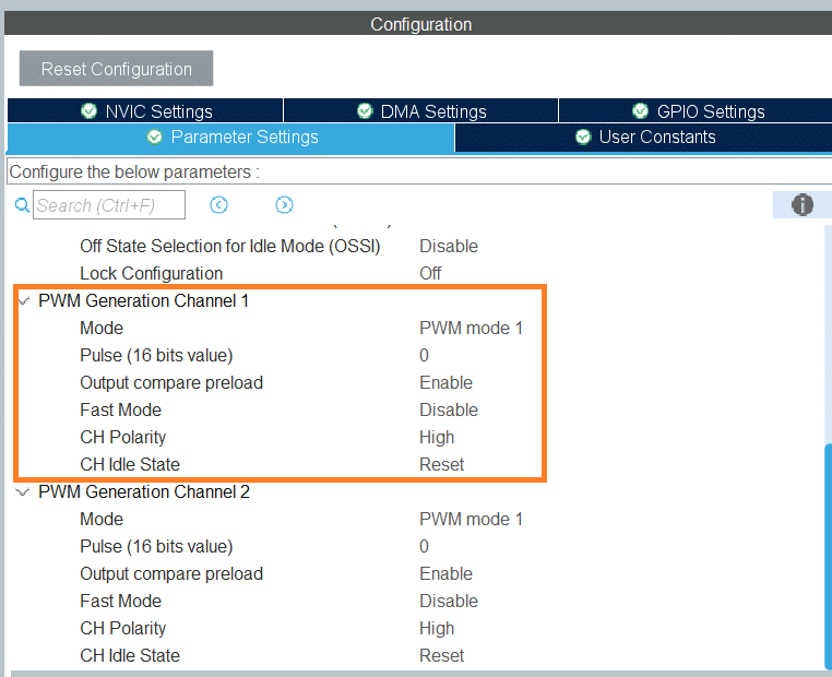
For Channel 1, mode is PWM mode 1 with a Pulse value of 0. Output Compare preload is enabled.
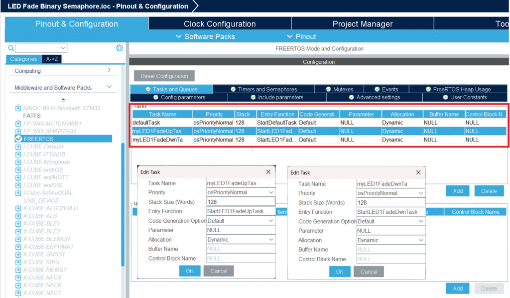
Setting up the Tasks
Here, two major tasks are made – StartLED1FadeUpTask and StartLED1FadeDwnTask. They have Normal Priority settings. As their name suggests, StartLED1FadeUpTask will take care of the LED1’s fading up sequence while StartLED1FadeDwnTask will take care of LED1’s fading down sequence.
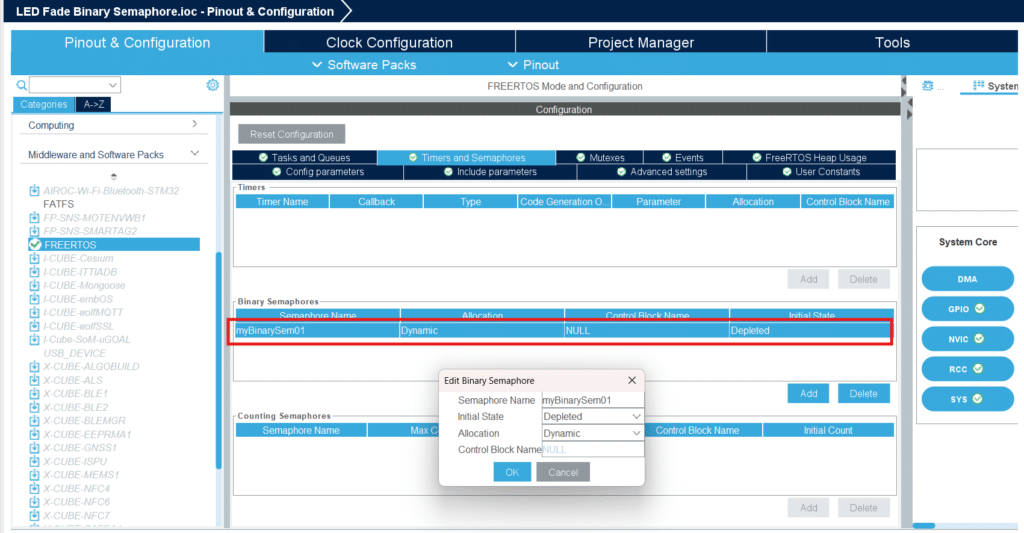
Setting up the Semaphore
Since we have a simple sequence, we’ll setup one Binary Semaphore My BinarySem01. Its initial state is setup as depleted although this doesn’t matter as we’ll take care of this in code later.
If everything has been setup correctly, you can generate code by clicking save.
Coding
The main code is listed below:
					/* USER CODE BEGIN Header */
/**
  ******************************************************************************
  * @file           : main.c
  * @brief          : Main program body
  ******************************************************************************
  * @attention
  *
  * Copyright (c) 2024 STMicroelectronics.
  * All rights reserved.
  *
  * This software is licensed under terms that can be found in the LICENSE file
  * in the root directory of this software component.
  * If no LICENSE file comes with this software, it is provided AS-IS.
  *
  ******************************************************************************
  */
/* USER CODE END Header */
/* Includes ------------------------------------------------------------------*/
#include "main.h"
#include "cmsis_os.h"

/* Private includes ----------------------------------------------------------*/
/* USER CODE BEGIN Includes */

/* USER CODE END Includes */

/* Private typedef -----------------------------------------------------------*/
/* USER CODE BEGIN PTD */

/* USER CODE END PTD */

/* Private define ------------------------------------------------------------*/
/* USER CODE BEGIN PD */

/* USER CODE END PD */

/* Private macro -------------------------------------------------------------*/
/* USER CODE BEGIN PM */

/* USER CODE END PM */

/* Private variables ---------------------------------------------------------*/
TIM_HandleTypeDef htim1;

osThreadId defaultTaskHandle;
osThreadId myLED1FadeUpTasHandle;
osThreadId myLED1FadeDwnTaHandle;
osSemaphoreId myBinarySem01Handle;
/* USER CODE BEGIN PV */
uint32_t return_val;
/* USER CODE END PV */

/* Private function prototypes -----------------------------------------------*/
void SystemClock_Config(void);
static void MX_GPIO_Init(void);
static void MX_TIM1_Init(void);
void StartDefaultTask(void const * argument);
void StartLED1FadeUpTask(void const * argument);
void StartLED1FadeDwnTask(void const * argument);

/* USER CODE BEGIN PFP */

/* USER CODE END PFP */

/* Private user code ---------------------------------------------------------*/
/* USER CODE BEGIN 0 */

/* USER CODE END 0 */

/**
  * @brief  The application entry point.
  * @retval int
  */
int main(void)
{

  /* USER CODE BEGIN 1 */

  /* USER CODE END 1 */

  /* MCU Configuration--------------------------------------------------------*/

  /* Reset of all peripherals, Initializes the Flash interface and the Systick. */
  HAL_Init();

  /* USER CODE BEGIN Init */

  /* USER CODE END Init */

  /* Configure the system clock */
  SystemClock_Config();

  /* USER CODE BEGIN SysInit */

  /* USER CODE END SysInit */

  /* Initialize all configured peripherals */
  MX_GPIO_Init();
  MX_TIM1_Init();
  /* USER CODE BEGIN 2 */
  HAL_TIM_PWM_Start(&htim1, TIM_CHANNEL_1);
  /* USER CODE END 2 */

  /* USER CODE BEGIN RTOS_MUTEX */
  /* add mutexes, ... */
  /* USER CODE END RTOS_MUTEX */

  /* Create the semaphores(s) */
  /* definition and creation of myBinarySem01 */
  osSemaphoreDef(myBinarySem01);
  myBinarySem01Handle = osSemaphoreCreate(osSemaphore(myBinarySem01), 1);

  /* USER CODE BEGIN RTOS_SEMAPHORES */
  /* add semaphores, ... */
  osSemaphoreWait(myBinarySem01Handle, 1);
  /* USER CODE END RTOS_SEMAPHORES */

  /* USER CODE BEGIN RTOS_TIMERS */
  /* start timers, add new ones, ... */
  /* USER CODE END RTOS_TIMERS */

  /* USER CODE BEGIN RTOS_QUEUES */
  /* add queues, ... */
  /* USER CODE END RTOS_QUEUES */

  /* Create the thread(s) */
  /* definition and creation of defaultTask */
  osThreadDef(defaultTask, StartDefaultTask, osPriorityNormal, 0, 128);
  defaultTaskHandle = osThreadCreate(osThread(defaultTask), NULL);

  /* definition and creation of myLED1FadeUpTas */
  osThreadDef(myLED1FadeUpTas, StartLED1FadeUpTask, osPriorityNormal, 0, 128);
  myLED1FadeUpTasHandle = osThreadCreate(osThread(myLED1FadeUpTas), NULL);

  /* definition and creation of myLED1FadeDwnTa */
  osThreadDef(myLED1FadeDwnTa, StartLED1FadeDwnTask, osPriorityNormal, 0, 128);
  myLED1FadeDwnTaHandle = osThreadCreate(osThread(myLED1FadeDwnTa), NULL);

  /* USER CODE BEGIN RTOS_THREADS */
  /* add threads, ... */
  /* USER CODE END RTOS_THREADS */

  /* Start scheduler */
  osKernelStart();

  /* We should never get here as control is now taken by the scheduler */

  /* Infinite loop */
  /* USER CODE BEGIN WHILE */
  while (1)
  {
    /* USER CODE END WHILE */

    /* USER CODE BEGIN 3 */
  }
  /* USER CODE END 3 */
}

/**
  * @brief System Clock Configuration
  * @retval None
  */
void SystemClock_Config(void)
{
  RCC_OscInitTypeDef RCC_OscInitStruct = {0};
  RCC_ClkInitTypeDef RCC_ClkInitStruct = {0};

  /** Initializes the RCC Oscillators according to the specified parameters
  * in the RCC_OscInitTypeDef structure.
  */
  RCC_OscInitStruct.OscillatorType = RCC_OSCILLATORTYPE_HSE;
  RCC_OscInitStruct.HSEState = RCC_HSE_ON;
  RCC_OscInitStruct.HSEPredivValue = RCC_HSE_PREDIV_DIV1;
  RCC_OscInitStruct.HSIState = RCC_HSI_ON;
  RCC_OscInitStruct.PLL.PLLState = RCC_PLL_ON;
  RCC_OscInitStruct.PLL.PLLSource = RCC_PLLSOURCE_HSE;
  RCC_OscInitStruct.PLL.PLLMUL = RCC_PLL_MUL9;
  if (HAL_RCC_OscConfig(&RCC_OscInitStruct) != HAL_OK)
  {
    Error_Handler();
  }

  /** Initializes the CPU, AHB and APB buses clocks
  */
  RCC_ClkInitStruct.ClockType = RCC_CLOCKTYPE_HCLK|RCC_CLOCKTYPE_SYSCLK
                              |RCC_CLOCKTYPE_PCLK1|RCC_CLOCKTYPE_PCLK2;
  RCC_ClkInitStruct.SYSCLKSource = RCC_SYSCLKSOURCE_PLLCLK;
  RCC_ClkInitStruct.AHBCLKDivider = RCC_SYSCLK_DIV1;
  RCC_ClkInitStruct.APB1CLKDivider = RCC_HCLK_DIV2;
  RCC_ClkInitStruct.APB2CLKDivider = RCC_HCLK_DIV1;

  if (HAL_RCC_ClockConfig(&RCC_ClkInitStruct, FLASH_LATENCY_2) != HAL_OK)
  {
    Error_Handler();
  }
}

/**
  * @brief TIM1 Initialization Function
  * @param None
  * @retval None
  */
static void MX_TIM1_Init(void)
{

  /* USER CODE BEGIN TIM1_Init 0 */

  /* USER CODE END TIM1_Init 0 */

  TIM_ClockConfigTypeDef sClockSourceConfig = {0};
  TIM_MasterConfigTypeDef sMasterConfig = {0};
  TIM_OC_InitTypeDef sConfigOC = {0};
  TIM_BreakDeadTimeConfigTypeDef sBreakDeadTimeConfig = {0};

  /* USER CODE BEGIN TIM1_Init 1 */

  /* USER CODE END TIM1_Init 1 */
  htim1.Instance = TIM1;
  htim1.Init.Prescaler = 16;
  htim1.Init.CounterMode = TIM_COUNTERMODE_UP;
  htim1.Init.Period = 100;
  htim1.Init.ClockDivision = TIM_CLOCKDIVISION_DIV1;
  htim1.Init.RepetitionCounter = 0;
  htim1.Init.AutoReloadPreload = TIM_AUTORELOAD_PRELOAD_ENABLE;
  if (HAL_TIM_Base_Init(&htim1) != HAL_OK)
  {
    Error_Handler();
  }
  sClockSourceConfig.ClockSource = TIM_CLOCKSOURCE_INTERNAL;
  if (HAL_TIM_ConfigClockSource(&htim1, &sClockSourceConfig) != HAL_OK)
  {
    Error_Handler();
  }
  if (HAL_TIM_PWM_Init(&htim1) != HAL_OK)
  {
    Error_Handler();
  }
  sMasterConfig.MasterOutputTrigger = TIM_TRGO_RESET;
  sMasterConfig.MasterSlaveMode = TIM_MASTERSLAVEMODE_DISABLE;
  if (HAL_TIMEx_MasterConfigSynchronization(&htim1, &sMasterConfig) != HAL_OK)
  {
    Error_Handler();
  }
  sConfigOC.OCMode = TIM_OCMODE_PWM1;
  sConfigOC.Pulse = 0;
  sConfigOC.OCPolarity = TIM_OCPOLARITY_HIGH;
  sConfigOC.OCNPolarity = TIM_OCNPOLARITY_HIGH;
  sConfigOC.OCFastMode = TIM_OCFAST_DISABLE;
  sConfigOC.OCIdleState = TIM_OCIDLESTATE_RESET;
  sConfigOC.OCNIdleState = TIM_OCNIDLESTATE_RESET;
  if (HAL_TIM_PWM_ConfigChannel(&htim1, &sConfigOC, TIM_CHANNEL_1) != HAL_OK)
  {
    Error_Handler();
  }
  if (HAL_TIM_PWM_ConfigChannel(&htim1, &sConfigOC, TIM_CHANNEL_2) != HAL_OK)
  {
    Error_Handler();
  }
  sBreakDeadTimeConfig.OffStateRunMode = TIM_OSSR_DISABLE;
  sBreakDeadTimeConfig.OffStateIDLEMode = TIM_OSSI_DISABLE;
  sBreakDeadTimeConfig.LockLevel = TIM_LOCKLEVEL_OFF;
  sBreakDeadTimeConfig.DeadTime = 0;
  sBreakDeadTimeConfig.BreakState = TIM_BREAK_DISABLE;
  sBreakDeadTimeConfig.BreakPolarity = TIM_BREAKPOLARITY_HIGH;
  sBreakDeadTimeConfig.AutomaticOutput = TIM_AUTOMATICOUTPUT_DISABLE;
  if (HAL_TIMEx_ConfigBreakDeadTime(&htim1, &sBreakDeadTimeConfig) != HAL_OK)
  {
    Error_Handler();
  }
  /* USER CODE BEGIN TIM1_Init 2 */

  /* USER CODE END TIM1_Init 2 */
  HAL_TIM_MspPostInit(&htim1);

}

/**
  * @brief GPIO Initialization Function
  * @param None
  * @retval None
  */
static void MX_GPIO_Init(void)
{
  GPIO_InitTypeDef GPIO_InitStruct = {0};
/* USER CODE BEGIN MX_GPIO_Init_1 */
/* USER CODE END MX_GPIO_Init_1 */

  /* GPIO Ports Clock Enable */
  __HAL_RCC_GPIOC_CLK_ENABLE();
  __HAL_RCC_GPIOD_CLK_ENABLE();
  __HAL_RCC_GPIOA_CLK_ENABLE();
  __HAL_RCC_GPIOB_CLK_ENABLE();

  /*Configure GPIO pin Output Level */
  HAL_GPIO_WritePin(LED_GPIO_Port, LED_Pin, GPIO_PIN_RESET);

  /*Configure GPIO pin : LED_Pin */
  GPIO_InitStruct.Pin = LED_Pin;
  GPIO_InitStruct.Mode = GPIO_MODE_OUTPUT_PP;
  GPIO_InitStruct.Pull = GPIO_NOPULL;
  GPIO_InitStruct.Speed = GPIO_SPEED_FREQ_LOW;
  HAL_GPIO_Init(LED_GPIO_Port, &GPIO_InitStruct);

/* USER CODE BEGIN MX_GPIO_Init_2 */
/* USER CODE END MX_GPIO_Init_2 */
}

/* USER CODE BEGIN 4 */

/* USER CODE END 4 */

/* USER CODE BEGIN Header_StartDefaultTask */
/**
  * @brief  Function implementing the defaultTask thread.
  * @param  argument: Not used
  * @retval None
  */
/* USER CODE END Header_StartDefaultTask */
void StartDefaultTask(void const * argument)
{
  /* USER CODE BEGIN 5 */
	osSemaphoreRelease(myBinarySem01Handle);
	/* Infinite loop */

  for(;;)
  {
    osDelay(10);
  }
  /* USER CODE END 5 */
}

/* USER CODE BEGIN Header_StartLED1FadeUpTask */
/**
* @brief Function implementing the myLED1FadeUpTas thread.
* @param argument: Not used
* @retval None
*/
/* USER CODE END Header_StartLED1FadeUpTask */
void StartLED1FadeUpTask(void const * argument)
{
  /* USER CODE BEGIN StartLED1FadeUpTask */

	uint32_t dutyCycle;
	uint32_t pulseLength;

	/* Infinite loop */
  for(;;)
  {
	  return_val = osSemaphoreWait(myBinarySem01Handle, osWaitForever);

	  for(dutyCycle=1;dutyCycle<100;dutyCycle++)
	  {
		  pulseLength = (htim1.Init.Period + 1) * dutyCycle / 100 - 1;
		  __HAL_TIM_SET_COMPARE(&htim1, TIM_CHANNEL_1, pulseLength);
		  osDelay(50);
	  }

	  return_val = osSemaphoreRelease(myBinarySem01Handle);

	  osDelay(50);
  }

  /* USER CODE END StartLED1FadeUpTask */
}

/* USER CODE BEGIN Header_StartLED1FadeDwnTask */
/**
* @brief Function implementing the myLED1FadeDwnTa thread.
* @param argument: Not used
* @retval None
*/
/* USER CODE END Header_StartLED1FadeDwnTask */
void StartLED1FadeDwnTask(void const * argument)
{
  /* USER CODE BEGIN StartLED1FadeDwnTask */
	uint32_t dutyCycle;
	uint32_t pulseLength;
	/* Infinite loop */
	  /* USER CODE BEGIN StartLED1Task */

	  /* Infinite loop */
	  for(;;)
	  {
		  return_val = osSemaphoreWait(myBinarySem01Handle, osWaitForever);

		  for(dutyCycle=100;dutyCycle>0;dutyCycle--)
		  {
			  pulseLength = (htim1.Init.Period + 1) * dutyCycle / 100 - 1;
			  __HAL_TIM_SET_COMPARE(&htim1, TIM_CHANNEL_1, pulseLength);
			  osDelay(50);
		  }

		  return_val = osSemaphoreRelease(myBinarySem01Handle);

		  osDelay(50);
	  }

  /* USER CODE END StartLED1FadeDwnTask */
}

/**
  * @brief  Period elapsed callback in non blocking mode
  * @note   This function is called  when TIM4 interrupt took place, inside
  * HAL_TIM_IRQHandler(). It makes a direct call to HAL_IncTick() to increment
  * a global variable "uwTick" used as application time base.
  * @param  htim : TIM handle
  * @retval None
  */
void HAL_TIM_PeriodElapsedCallback(TIM_HandleTypeDef *htim)
{
  /* USER CODE BEGIN Callback 0 */

  /* USER CODE END Callback 0 */
  if (htim->Instance == TIM4) {
    HAL_IncTick();
  }
  /* USER CODE BEGIN Callback 1 */

  /* USER CODE END Callback 1 */
}

/**
  * @brief  This function is executed in case of error occurrence.
  * @retval None
  */
void Error_Handler(void)
{
  /* USER CODE BEGIN Error_Handler_Debug */
  /* User can add his own implementation to report the HAL error return state */
  __disable_irq();
  while (1)
  {
  }
  /* USER CODE END Error_Handler_Debug */
}

#ifdef  USE_FULL_ASSERT
/**
  * @brief  Reports the name of the source file and the source line number
  *         where the assert_param error has occurred.
  * @param  file: pointer to the source file name
  * @param  line: assert_param error line source number
  * @retval None
  */
void assert_failed(uint8_t *file, uint32_t line)
{
  /* USER CODE BEGIN 6 */
  /* User can add his own implementation to report the file name and line number,
     ex: printf("Wrong parameters value: file %s on line %d\r\n", file, line) */
  /* USER CODE END 6 */
}
#endif /* USE_FULL_ASSERT */
The PWM is started early in the initialization code with a 0% Duty Cycle through HAL_TIM_PWM_Start(&htim1, TIM_CHANNEL_1).
					  /* Initialize all configured peripherals */
  MX_GPIO_Init();
  MX_TIM1_Init();
  /* USER CODE BEGIN 2 */
  HAL_TIM_PWM_Start(&htim1, TIM_CHANNEL_1);
  /* USER CODE END 2 */
The binary semaphore myBinarySem01Handle is ensured to be depleted initially by calling osSemaphoreWait().
					  /* Create the semaphores(s) */
  /* definition and creation of myBinarySem01 */
  osSemaphoreDef(myBinarySem01);
  myBinarySem01Handle = osSemaphoreCreate(osSemaphore(myBinarySem01), 1);

  /* USER CODE BEGIN RTOS_SEMAPHORES */
  /* add semaphores, ... */
  osSemaphoreWait(myBinarySem01Handle, 1);
  /* USER CODE END RTOS_SEMAPHORES */
The default task StartDefaultTask() will start the fading sequence by issuing an osSemaphoreRelease() (or Semaphore Give).
					void StartDefaultTask(void const * argument)
{
  /* USER CODE BEGIN 5 */
	osSemaphoreRelease(myBinarySem01Handle);
	/* Infinite loop */

  for(;;)
  {
    osDelay(10);
  }
  /* USER CODE END 5 */
}
This token in turn will be received by either the Fade Up or Fade Down task, whichever comes first, through the osSemaphoreWait() API. Note that osSemaphoreWait() has osWaitForever as parameter. This means it will block the remaining code forever unless it receives the token. After the fade up (or fade down) sequence finishes, an osSemaphoreRelease() is made. Thereafter an osDelay() follows meaning this function will block itself for other tasks to continue.
					void StartLED1FadeUpTask(void const * argument)
{
  /* USER CODE BEGIN StartLED1FadeUpTask */

	uint32_t dutyCycle;
	uint32_t pulseLength;

	/* Infinite loop */
  for(;;)
  {
	  return_val = osSemaphoreWait(myBinarySem01Handle, osWaitForever);

	  for(dutyCycle=1;dutyCycle<100;dutyCycle++)
	  {
		  pulseLength = (htim1.Init.Period + 1) * dutyCycle / 100 - 1;
		  __HAL_TIM_SET_COMPARE(&htim1, TIM_CHANNEL_1, pulseLength);
		  osDelay(50);
	  }

	  return_val = osSemaphoreRelease(myBinarySem01Handle);

	  osDelay(50);
  }

  /* USER CODE END StartLED1FadeUpTask */
}
This osSemaphoreRelaese() will be taken by the osSemaphoreWait() statement on the StartLED1FadeDwnTask().
					void StartLED1FadeDwnTask(void const * argument)
{
  /* USER CODE BEGIN StartLED1FadeDwnTask */
	uint32_t dutyCycle;
	uint32_t pulseLength;
	/* Infinite loop */
	  /* USER CODE BEGIN StartLED1Task */

	  /* Infinite loop */
	  for(;;)
	  {
		  return_val = osSemaphoreWait(myBinarySem01Handle, osWaitForever);

		  for(dutyCycle=100;dutyCycle>0;dutyCycle--)
		  {
			  pulseLength = (htim1.Init.Period + 1) * dutyCycle / 100 - 1;
			  __HAL_TIM_SET_COMPARE(&htim1, TIM_CHANNEL_1, pulseLength);
			  osDelay(50);
		  }

		  return_val = osSemaphoreRelease(myBinarySem01Handle);

		  osDelay(50);
	  }

  /* USER CODE END StartLED1FadeDwnTask */
}
Thereafter, after the LED fades down, it will continue to do an osSemaphoreRelease() and an osDelay(). This token, in turn, will be received by the next-in-line task which should be the start of StartLED1FadeUpTask() again. This will effectively continue a fade up – fade down sequence pattern indefinitely.
The next part will continue fading two LEDs in an alternate fashion using more than one binary semaphore.
SHOP THIS PROJECT
-
Sale!

ST-Link V2 Mini In-Circuit Programmer and Debugger for STM8 / STM32
$31.95Original price was: $31.95.$16.95Current price is: $16.95. Add to cart