Would you like to do advanced debug functions on your STM32 like trace plot data? Read below to find out.
Introduction
There are times when you need to see the behavior of a series of data you’ve acquired from the outside world. At first, these data may be noisy, raw, and unfiltered. It might be impractical to feed them to a digital system. You may pass these data to a filter to smoothen them out. You can also apply DSP (Digital Signal Processing) on them. With this, it’s a good idea to have STM32 software (STM32CubeIDE) plot a trace or graph of these data to get a glimpse of their behavior in real-time.
Fortunately, STM32CubeIDE can easily plot trace data using its advanced SWV (Serial Wire Viewer) Debug Trace feature.
How to do a SWV Data Trace Timeline Graph
Example Code
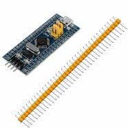
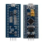
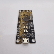
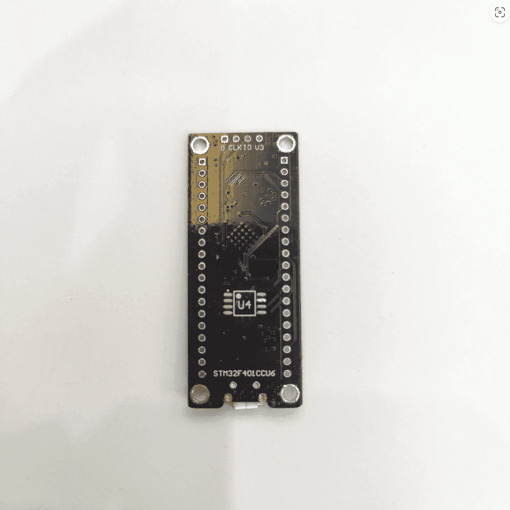
As an example, we can monitor ADC data on an STM32F411CEU Black Pill development board. Below is the code that you can use. This code uses ADC Interrupt to acquire values and a state machine is implemented to run it.
					/* USER CODE BEGIN Header */
/**
  ******************************************************************************
  * @file           : main.c
  * @brief          : Main program body
  ******************************************************************************
  * @attention
  *
  * Copyright (c) 2024 STMicroelectronics.
  * All rights reserved.
  *
  * This software is licensed under terms that can be found in the LICENSE file
  * in the root directory of this software component.
  * If no LICENSE file comes with this software, it is provided AS-IS.
  *
  ******************************************************************************
  */
/* USER CODE END Header */
/* Includes ------------------------------------------------------------------*/
#include "main.h"

/* Private includes ----------------------------------------------------------*/
/* USER CODE BEGIN Includes */
#include <stdio.h>
/* USER CODE END Includes */

/* Private typedef -----------------------------------------------------------*/
/* USER CODE BEGIN PTD */
typedef enum {ADC_Start, ADC_Run, ADC_Stop} ADC_states_t;
/* USER CODE END PTD */

/* Private define ------------------------------------------------------------*/
/* USER CODE BEGIN PD */

/* USER CODE END PD */

/* Private macro -------------------------------------------------------------*/
/* USER CODE BEGIN PM */

/* USER CODE END PM */

/* Private variables ---------------------------------------------------------*/
ADC_HandleTypeDef hadc1;

/* USER CODE BEGIN PV */
int ADC_IN0_flag;
ADC_states_t ADC_states;
int ADC_Value;
/* USER CODE END PV */

/* Private function prototypes -----------------------------------------------*/
void SystemClock_Config(void);
static void MX_GPIO_Init(void);
static void MX_ADC1_Init(void);
/* USER CODE BEGIN PFP */

/* USER CODE END PFP */

/* Private user code ---------------------------------------------------------*/
/* USER CODE BEGIN 0 */

/* USER CODE END 0 */

/**
  * @brief  The application entry point.
  * @retval int
  */
int main(void)
{

  /* USER CODE BEGIN 1 */

  /* USER CODE END 1 */

  /* MCU Configuration--------------------------------------------------------*/

  /* Reset of all peripherals, Initializes the Flash interface and the Systick. */
  HAL_Init();

  /* USER CODE BEGIN Init */

  /* USER CODE END Init */

  /* Configure the system clock */
  SystemClock_Config();

  /* USER CODE BEGIN SysInit */

  /* USER CODE END SysInit */

  /* Initialize all configured peripherals */
  MX_GPIO_Init();
  MX_ADC1_Init();
  /* USER CODE BEGIN 2 */

  /* USER CODE END 2 */

  /* Infinite loop */
  /* USER CODE BEGIN WHILE */
  while (1)
  {
	  HAL_Delay(500);

	  switch (ADC_states) {
		case ADC_Start:
			HAL_ADC_Start_IT(&hadc1);
			ADC_states = ADC_Run;
			break;
		case ADC_Run:
			if(ADC_IN0_flag == 1)
			{
			  ADC_Value = (int)HAL_ADC_GetValue(&hadc1);
			  printf("ADC value: %i", ADC_Value);
			  ADC_IN0_flag = 0;
			  ADC_states = ADC_Stop;
			}
			break;
		case ADC_Stop:
			HAL_ADC_Stop_IT(&hadc1);
			ADC_states = ADC_Start;
			break;
		default:
			break;
	}


    /* USER CODE END WHILE */

    /* USER CODE BEGIN 3 */
  }
  /* USER CODE END 3 */
}

/**
  * @brief System Clock Configuration
  * @retval None
  */
void SystemClock_Config(void)
{
  RCC_OscInitTypeDef RCC_OscInitStruct = {0};
  RCC_ClkInitTypeDef RCC_ClkInitStruct = {0};

  /** Configure the main internal regulator output voltage
  */
  __HAL_RCC_PWR_CLK_ENABLE();
  __HAL_PWR_VOLTAGESCALING_CONFIG(PWR_REGULATOR_VOLTAGE_SCALE1);

  /** Initializes the RCC Oscillators according to the specified parameters
  * in the RCC_OscInitTypeDef structure.
  */
  RCC_OscInitStruct.OscillatorType = RCC_OSCILLATORTYPE_HSE;
  RCC_OscInitStruct.HSEState = RCC_HSE_ON;
  RCC_OscInitStruct.PLL.PLLState = RCC_PLL_ON;
  RCC_OscInitStruct.PLL.PLLSource = RCC_PLLSOURCE_HSE;
  RCC_OscInitStruct.PLL.PLLM = 12;
  RCC_OscInitStruct.PLL.PLLN = 96;
  RCC_OscInitStruct.PLL.PLLP = RCC_PLLP_DIV2;
  RCC_OscInitStruct.PLL.PLLQ = 5;
  if (HAL_RCC_OscConfig(&RCC_OscInitStruct) != HAL_OK)
  {
    Error_Handler();
  }

  /** Initializes the CPU, AHB and APB buses clocks
  */
  RCC_ClkInitStruct.ClockType = RCC_CLOCKTYPE_HCLK|RCC_CLOCKTYPE_SYSCLK
                              |RCC_CLOCKTYPE_PCLK1|RCC_CLOCKTYPE_PCLK2;
  RCC_ClkInitStruct.SYSCLKSource = RCC_SYSCLKSOURCE_PLLCLK;
  RCC_ClkInitStruct.AHBCLKDivider = RCC_SYSCLK_DIV1;
  RCC_ClkInitStruct.APB1CLKDivider = RCC_HCLK_DIV2;
  RCC_ClkInitStruct.APB2CLKDivider = RCC_HCLK_DIV1;

  if (HAL_RCC_ClockConfig(&RCC_ClkInitStruct, FLASH_LATENCY_3) != HAL_OK)
  {
    Error_Handler();
  }
}

/**
  * @brief ADC1 Initialization Function
  * @param None
  * @retval None
  */
static void MX_ADC1_Init(void)
{

  /* USER CODE BEGIN ADC1_Init 0 */

  /* USER CODE END ADC1_Init 0 */

  ADC_ChannelConfTypeDef sConfig = {0};

  /* USER CODE BEGIN ADC1_Init 1 */

  /* USER CODE END ADC1_Init 1 */

  /** Configure the global features of the ADC (Clock, Resolution, Data Alignment and number of conversion)
  */
  hadc1.Instance = ADC1;
  hadc1.Init.ClockPrescaler = ADC_CLOCK_SYNC_PCLK_DIV4;
  hadc1.Init.Resolution = ADC_RESOLUTION_12B;
  hadc1.Init.ScanConvMode = DISABLE;
  hadc1.Init.ContinuousConvMode = DISABLE;
  hadc1.Init.DiscontinuousConvMode = DISABLE;
  hadc1.Init.ExternalTrigConvEdge = ADC_EXTERNALTRIGCONVEDGE_NONE;
  hadc1.Init.ExternalTrigConv = ADC_SOFTWARE_START;
  hadc1.Init.DataAlign = ADC_DATAALIGN_RIGHT;
  hadc1.Init.NbrOfConversion = 1;
  hadc1.Init.DMAContinuousRequests = DISABLE;
  hadc1.Init.EOCSelection = ADC_EOC_SINGLE_CONV;
  if (HAL_ADC_Init(&hadc1) != HAL_OK)
  {
    Error_Handler();
  }

  /** Configure for the selected ADC regular channel its corresponding rank in the sequencer and its sample time.
  */
  sConfig.Channel = ADC_CHANNEL_0;
  sConfig.Rank = 1;
  sConfig.SamplingTime = ADC_SAMPLETIME_3CYCLES;
  if (HAL_ADC_ConfigChannel(&hadc1, &sConfig) != HAL_OK)
  {
    Error_Handler();
  }
  /* USER CODE BEGIN ADC1_Init 2 */

  /* USER CODE END ADC1_Init 2 */

}

/**
  * @brief GPIO Initialization Function
  * @param None
  * @retval None
  */
static void MX_GPIO_Init(void)
{
/* USER CODE BEGIN MX_GPIO_Init_1 */
/* USER CODE END MX_GPIO_Init_1 */

  /* GPIO Ports Clock Enable */
  __HAL_RCC_GPIOH_CLK_ENABLE();
  __HAL_RCC_GPIOA_CLK_ENABLE();
  __HAL_RCC_GPIOB_CLK_ENABLE();

/* USER CODE BEGIN MX_GPIO_Init_2 */
/* USER CODE END MX_GPIO_Init_2 */
}

/* USER CODE BEGIN 4 */
int _write(int file, char *ptr, int len)
{
  (void)file;
  int DataIdx;

  for (DataIdx = 0; DataIdx < len; DataIdx++)
  {
    //__io_putchar(*ptr++);
	  ITM_SendChar(*ptr++);
  }
  return len;
}

void HAL_ADC_ConvCpltCallback(ADC_HandleTypeDef *hadc)
{
  /* Prevent unused argument(s) compilation warning */
  UNUSED(hadc);
  /* NOTE : This function Should not be modified, when the callback is needed,
            the HAL_ADC_ConvCpltCallback could be implemented in the user file
   */

  ADC_IN0_flag = 1;
}

/* USER CODE END 4 */

/**
  * @brief  This function is executed in case of error occurrence.
  * @retval None
  */
void Error_Handler(void)
{
  /* USER CODE BEGIN Error_Handler_Debug */
  /* User can add his own implementation to report the HAL error return state */
  __disable_irq();
  while (1)
  {
  }
  /* USER CODE END Error_Handler_Debug */
}

#ifdef  USE_FULL_ASSERT
/**
  * @brief  Reports the name of the source file and the source line number
  *         where the assert_param error has occurred.
  * @param  file: pointer to the source file name
  * @param  line: assert_param error line source number
  * @retval None
  */
void assert_failed(uint8_t *file, uint32_t line)
{
  /* USER CODE BEGIN 6 */
  /* User can add his own implementation to report the file name and line number,
     ex: printf("Wrong parameters value: file %s on line %d\r\n", file, line) */
  /* USER CODE END 6 */
}
#endif /* USE_FULL_ASSERT */
Enable SWV Debug Function
Next, enable the SWV function as was done in DEBUG AN STM32 WITH PRINTF USING ONLY AN ST-LINK. You can start debugging after this step.
Define SWV Trace Data
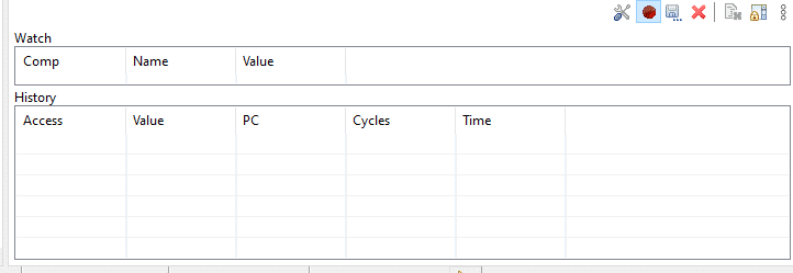
After this, show the SWV Data Trace window by going through Window -> Show Views -> SWV -> SWV Data Trace. This window will let you define the global variables you want monitored.
Next, define the global variables you want to be monitored on Data Trace. Here ADC_Value is used.
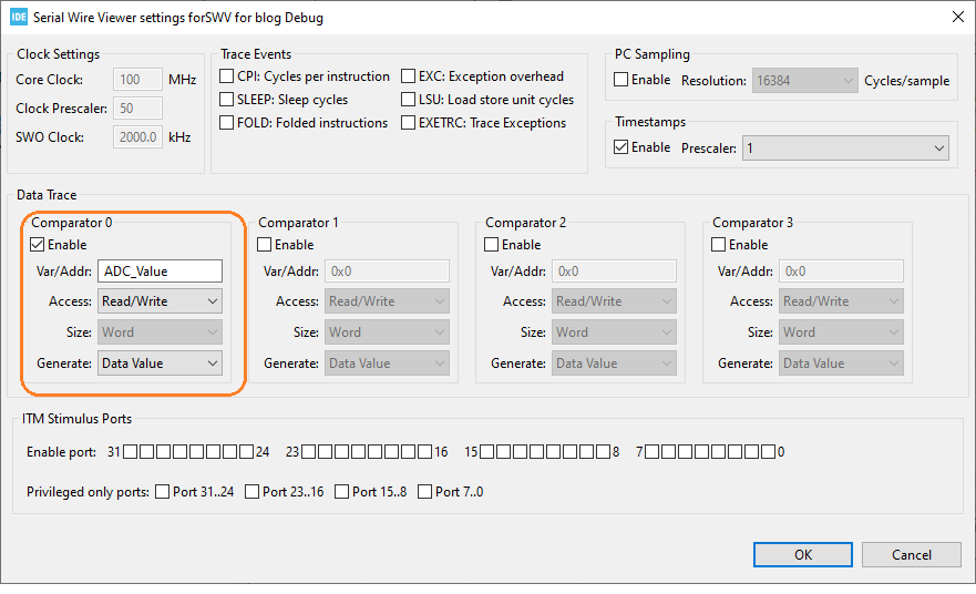
Click OK when finished.
Now if you continue to resume your debug session, you should see the ADC_Value variable being populated with values in real time.
Enable SWV Data Trace Timeline Graph
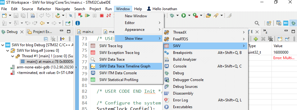
Click Show View -> SWV -> SWV Data Trace Timeline Graph.

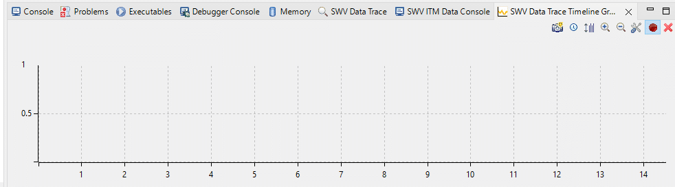
As you can see above, there is an empty graph. When you resume debugging, this graph should be populated with your ADC values in real-time. The Y–axis will adjust to the magnitude of the ADC values. You can adjust time settings through the zoom-in and zoom-out icons. If you want to start over again to adjust your values, simply hit the Remove all collected data (X) icon.
Improving or Filtering Your Data
You’ll have to implement different techniques to improve the quality of your sample data. One example is to do averaging or oversampling on your raw ADC values. You can refer to ADC OVERSAMPLING TO DECREASE NOISE AND INCREASE RESOLUTION as a guide. With this, you can apply the oversampled values to another SWV Data Trace Variable and see how it differs with your raw data.
SHOP THIS PROJECT
-
Sale!

ST-Link V2 Mini In-Circuit Programmer and Debugger for STM8 / STM32
$31.95Original price was: $31.95.$16.95Current price is: $16.95. Add to cart