12V Adjustable 0 To 10 Second Delay Relay Module – NE555
OPERATIONAL OVERVIEW:
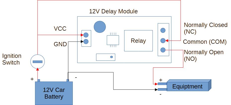
This module ideally creates a set delay so that your car equipment is not damaged during the ignition process. The wiring diagram can be seen below.
When power is applied to the module’s input, it activates the user-set timer and turns on the power LED. Once the timer reaches its pre-set time, it triggers the relay to switch on and power your equipment. Depending on how you wired the relay, the output determines whether it applies or disconnects power. The module will hold this position until input power is removed.
Applications:
- Car infotainment equipment (DVD, MP3 Player, Etc.)
- Cam Recorder
- Multimedia Speakers/Amplifiers
PINOUT:
Input:
- VCC: Positive
- GND: Negative
Output:
- NC / CB: Relay Normally Closed *
- COM: Relay Common
- NO / CK: Relay Normally Open *
* When setting up the output, you only connect 1 of the outputs (NC / CB or NO / CK)
* The boards’ Labeling of the outputs varies. We have seen them labeled as NC & CB for the normally closed relay output and NO & CK for the normally open relay output.
TIMER:
Adjusting the timer is done via the trim pot, which can be turned in either direction to increase or decrease the timer. The trim pot is multiturn, requiring multiple resolutions to effect change.
Clockwise: Increase time
Anti-clockwise: Decrease time
TECHNICAL SPECIFICATIONS:
- Input voltage: 12V DC
- Control voltage: 220V AC (MAX) / 30V DC (MAX)
- Load: 2000W (MAX)
- Timer: 0 – 10 seconds
- Board dimensions: 77mm (L) x 23mm (W) x 18mm (H)
Wiring Diagram