5V 2/4/8 Channel Relay Modules with Optocoupler User’s Guide
Introduction
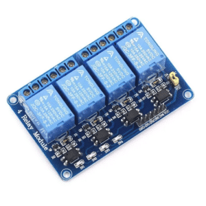
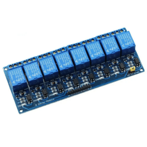
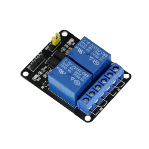
These 5V multi-channel relay modules are convenient devices for controlling an external load using low power/low voltage devices such as an Arduino. These relays are usually active low devices (meaning the relays are activated with low voltage logic). Additionally, there is a jumper-based optocoupler circuit to isolate the input relay circuit from the device power, preventing unwanted noise that can affect the relays’ inputs.
Specifications
- Operating Voltage: 5V DC
- Trigger Current: 5mA
- Relay Maximum Contact Voltage: 250VAC, 30VDC
- Relay Maximum Current: 10A
- Trigger Mode: Active Low
- Indicator LEDs: Power supply indicator and relay status indicators
How to Operate the Device
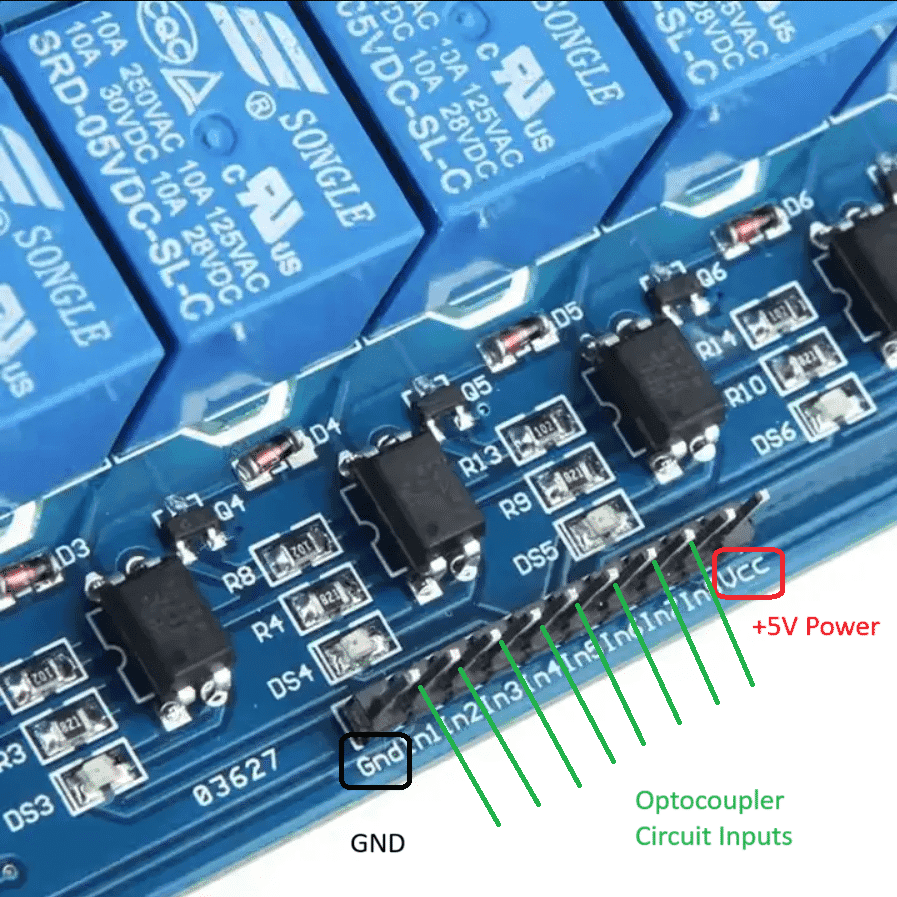
Simply supply the module with 5V DC and GND through the terminals below. Additionally, connect the 5V active low input pins (Optocoupler circuit inputs) to your Arduino ports to be able to control the relays.
How to Provide Opto-isolation
There is an available jumper that can provide isolation for the input circuitry of the relay. If you short the jumper, there will be no isolation since device power and input relay circuit power are the same. When opening the jumper, you must provide power to the JD.VCC pin which also powers the input opto-isolator circuit of the relay.
How to Interface to Different Logic Voltages
The device is triggered with a 5V active low input logic that is compatible with most Arduino modules. If you have a 3.3V module, it’s recommended to use a 3.3V to 5V logic level converter.