Have a primer on using basic interrupts on an ESP32 through this article.
Introduction
A flexible microcontroller employs an interrupt system that can accomplish certain internal or peripheral interrupt routines immediately. Here you’ll learn basic interrupts on an ESP32 microcontroller. Before continuing, you may want to check INTERRUPT SERVICE ROUTINES: BEST PRACTICES to know how to write efficient interrupt service routines.
Basic Structure of an ESP32 Interrupt
An ESP32 (specifically, an ESP32-S3), has 32 available interrupt slots each for its 2 CPU cores. These interrupts can be divided into 7 priority levels and each interrupt has a fixed priority. For the peripheral interrupts, an interrupt multiplexer is employed so that the interrupt can be processed efficiently by its two CPUs.
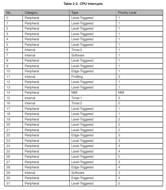
Below are the CPU interrupt slots available for the ESP32-S3
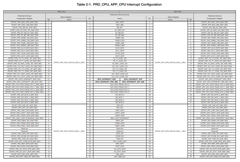
There are several actual interrupt sources available for the ESP32-S3. Below is a complete list of the peripheral interrupt sources for this microcontroller. These sources can be allocated to a CPU interrupt slot when activated.

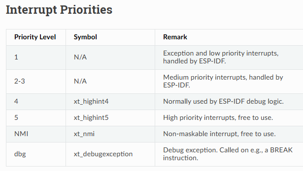
Below are the 7 interrupt priorities of the ESP32-S3 that can be routed successfully through interrupt allocation and the interrupt matrix.
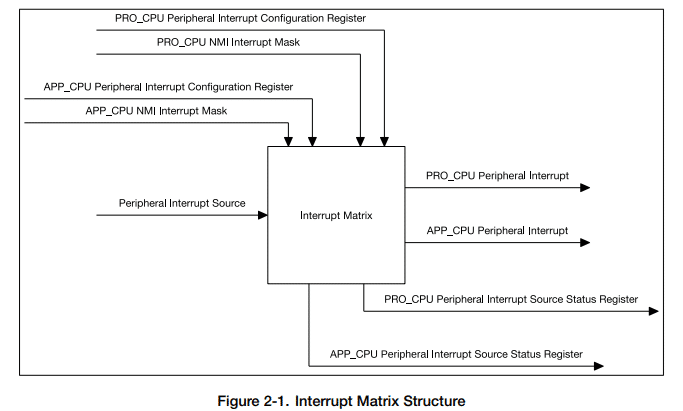
Here is the Interrupt Matrix for the ESP32-S3
However, as you’ll see later, most of the intricacies of interrupt handling has been abstracted away from the user through a set of interrupt ESP-IDF APIs.
How to setup an ESP32 Interrupt
To set up an interrupt, you may need to configure a peripheral to use interrupts.
Below is a case where an external interrupt is enabled to use an ISR.
gpio_install_isr_service(0);
After that, prepare a function handler to take care of the processes needed to execute after the interrupt occurs.
Below is a case of a hardware timer using a timer_callback function handler which will be useful later.
					    const esp_timer_create_args_t my_timer_args = {
        .callback = &timer_callback,
        .name = "my_timer"
    };
    esp_timer_handle_t timer_handler;

    esp_timer_create(&my_timer_args, &timer_handler);
    esp_timer_start_periodic(timer_handler, 2000000); // 2 second
The function handler is usually also the ISR (Interrupt Service Routine), so make sure to keep it as short as possible. Most of the times, the ISR should be allocated with an IRAM_ATTR to keep it fast and efficient. IRAM_ATTR means the function is allocated in RAM instead of flash.
Here is a use case using a buttonInterrupt handler for an EXT pin interrupt.
					void IRAM_ATTR buttonInterrupt()
{
    button_flag = 1;
}
Here is a use case using a timer_callback handler as ISR for a timer event.
					void IRAM_ATTR timer_callback(void* arg) {
    static int toggle = 0;
    gpio_set_level(LED_PIN, toggle);
    toggle = !toggle;
}
Example Use Cases
Interrupt on An External GPIO Pin
Here is an example use case of employing an interrupt on an external GPIO pin.
					#include <stdio.h>
#include <driver\gpio.h>
#include <freertos\FreeRTOS.h>
#include <freertos\task.h>

// Define the GPIO pin for the interrupt
#define PUSH_BUTTON1 GPIO_NUM_10

// LED Pin
#define LED_G GPIO_NUM_5

volatile BaseType_t button_flag, led_flag;

void IRAM_ATTR buttonInterrupt()
{
    button_flag = 1;
}

void app_main(void)
{
    button_flag = 0;

    // LED Pin
    gpio_set_direction(LED_G, GPIO_MODE_OUTPUT);

    //EXT Interrupt
    gpio_set_direction(PUSH_BUTTON1, GPIO_MODE_INPUT);
    gpio_set_pull_mode(PUSH_BUTTON1, GPIO_PULLUP_ENABLE);


    gpio_set_intr_type(PUSH_BUTTON1, GPIO_INTR_LOW_LEVEL);
    gpio_install_isr_service(0);
    gpio_isr_handler_add(PUSH_BUTTON1, buttonInterrupt, NULL);

    for(;;)
    {
        if(button_flag)
        {
            led_flag ^= 1;

            {
                vTaskDelay(300/portTICK_PERIOD_MS); // debounce
                gpio_set_level(LED_G, led_flag); //gpio_set_level(PUSH_BUTTON1, !gpio_get_level(PUSH_BUTTON1)));
                button_flag = 0;
            }

        }

        vTaskDelay(100/portTICK_PERIOD_MS);
    }

}
The EXT interrupt is set up through the following statements. gpio_set_intr_type() sets the edge or level of the pin interrupt, gpio_install_isr_service() installs the gpio interrupt service, while gpio_isr_handler_add(), registers the EXT interrupt pin handler function buttonInterrupt().
					    //EXT Interrupt
    gpio_set_direction(PUSH_BUTTON1, GPIO_MODE_INPUT);
    gpio_set_pull_mode(PUSH_BUTTON1, GPIO_PULLUP_ENABLE);


    gpio_set_intr_type(PUSH_BUTTON1, GPIO_INTR_LOW_LEVEL);
    gpio_install_isr_service(0);
    gpio_isr_handler_add(PUSH_BUTTON1, buttonInterrupt, NULL);
When an EXT pin interrupt happens, the handler function buttonInterrupt() executes which is the ISR. The ISR simply sets a button_flag that is polled in main to toggle an LED.
					void IRAM_ATTR buttonInterrupt()
{
    button_flag = 1;
}
Interrupt on a Timer Event
Below is the code for interrupt on a periodic timer event.
					#include <stdio.h>
#include <driver\gpio.h>
#include <freertos\FreeRTOS.h>
#include <freertos\task.h>
#include <esp_timer.h>

#define LED_G GPIO_NUM_5

volatile BaseType_t toggle;

void IRAM_ATTR timer_callback(void *arg)
{
    static int toggle = 0;
    gpio_set_level(LED_G, toggle);
    toggle ^= 1;
}

void app_main(void)
{
    gpio_set_direction(LED_G, GPIO_MODE_OUTPUT);

    const esp_timer_create_args_t my_timer_args = {
        .callback = &timer_callback,
        .name = "my_timer"
    };
    esp_timer_handle_t timer_handler;

    esp_timer_create(&my_timer_args, &timer_handler);
    esp_timer_start_periodic(timer_handler, 1000000);

    for(;;)
    {

        vTaskDelay(100/portTICK_PERIOD_MS);
    }
}
The code to setup the timer interrupt contains a my_timer_args list containig the timer_callback function and the timer name. The argument list is needed for the esp_timer_create() function that creates the timer. A timer_handler is specifiied to be able to pinpoint the timer. The timer is started with the esp_timer_start_periodic() function.
					    const esp_timer_create_args_t my_timer_args = {
        .callback = &timer_callback,
        .name = "my_timer"
    };
    esp_timer_handle_t timer_handler;

    esp_timer_create(&my_timer_args, &timer_handler);
    esp_timer_start_periodic(timer_handler, 1000000);
The timer_callback() is the ISR which simply toggles an LED when the corresponding timer period expires.
					void IRAM_ATTR timer_callback(void *arg)
{
    static int toggle = 0;
    gpio_set_level(LED_G, toggle);
    toggle ^= 1;
}

