Arduino, like all microcontrollers, has a limited number of pins. An Arduino typically has 14 digital pins. So, what if you need to control 7 LEDs or other devices? Normally, you would need to use 7 individual digital pins, which is quite a lot.
Today, we will learn how to overcome this limitation by using the power of shift registers! With a shift register, you can control 7 or more digital outputs using only 3 Arduino digital pins. The circuit may be a bit complex, and the working principles can be intricate, but this technique is incredibly useful and worth learning.
What is a Shift Register?
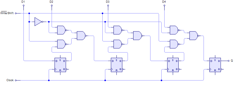
A shift register is a type of sequential logic circuit used for the storage or transfer of binary data. Shift registers hold data in memory and move or “shift” it to the required positions with each clock pulse. The register is loaded with serial data, one bit at a time, and the stored data is available at the output in parallel form.
Explaining shift registers in detail can be complex, as it is a broad topic often covered in university courses. If you’re interested in understanding how shift registers work, I highly recommend exploring the following resources in sequential order:
If the above video has been removed, a backup as been made for archive purposes: Click Here.
If the above video has been removed, a backup as been made for archive purposes: Click Here.
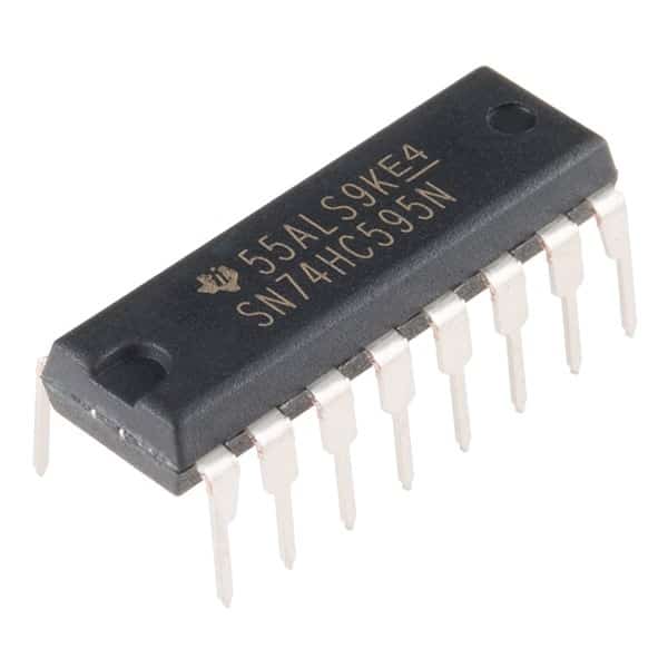
Shift Register SN74HC595
For our tutorial today, we will be using the SN74HC595 shift register IC.
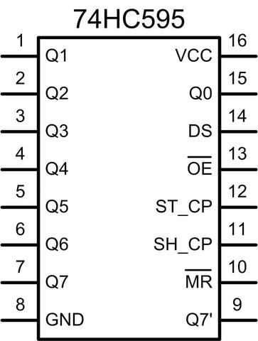
The SN74HC595 IC contains an 8-bit serial-in, parallel-out shift register that feeds an 8-bit D-type storage register. The storage register features parallel 3-state outputs. Separate clocks are provided for both the shift register and the storage register. The shift register includes a direct overriding clear (SRCLR) input, a serial (SER) input, and serial outputs for cascading. When the output-enable (OE) input is high, the outputs enter a high-impedance state.
SN74HC595 Pinout
Circuit DiaGRAM
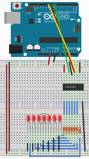
The circuit may look a bit messy and complex, but don’t worry—it becomes much simpler once you start implementing it.
The Code
					int DS_pin = 8;
int STCP_pin = 9;
int SHCP_pin = 10;

void setup() {
pinMode(DS_pin,OUTPUT);
pinMode(STCP_pin,OUTPUT);
pinMode(SHCP_pin,OUTPUT);

writereg();
}

boolean registers[8];

void writereg() {
digitalWrite(STCP_pin, LOW);

for (int i = 7; i>=0; i--) {
digitalWrite(SHCP_pin, LOW);
digitalWrite(DS_pin, registers[i] );
digitalWrite(SHCP_pin, HIGH);
}

digitalWrite(STCP_pin, HIGH);
}

void loop() {
for(int i = 0; i<8; i++) {
registers[i] = HIGH;
delay(1000);
writereg();
}

for(int i = 7; i>0; i--) {
registers[i] = LOW;
delay(1000);
writereg();

}
}
How The Code Works
This code turns on all the LEDs one by one, then turns them off again one by one. The working procedure of the shift register and the code may seem a little complex, but it becomes fascinating once you understand it.
Basically, while keeping the SHCP pin low, we set each of the bits by sending pulses. After setting all 8 bits or sending all the pulses to the DS pin, we give a pulse to the STCP pin. This executes our configured bit pattern, turning the LEDs on as desired. The LEDs are turned on one by one, and then turned off one by one.
To understand the process more clearly, we recommend watching the video “How Shift Registers Work,” referenced above. It explains the process in detail.
If you have successfully implemented the project shown here, congratulations! You have moved beyond beginner and basic circuits and projects.