If you’re looking for a reliable yet cost-effective water level alarm made from stocked CMOS logic gates this is a good article to check.
Introduction
A water level alarm is a very useful gadget especially if you have to monitor water overflow levels on various locations. Say, for example, you have an overhead tank that needs to be checked if it has filled up while running your water pump. You could also use this device to warn you before your bathtub overflows; a really neat and simple way to keep the other parts of your bathroom neat and dry.
That being said, to keep things simple and portable, the proposed water level alarm uses a popular off-the shelf CMOS logic NAND gate and other easy to source components.
What's Special about a CMOS NAND Gate?
There are 3 things that are special about a CMOS NAND gate enough for it to be used as a simple water level alarm:
Classic CMOS logic gates operate at around +3V to +16V making them work from a +9V battery without the need for a voltage regulator.
The logic level threshold of a classic CMOS is 0.3 * Vdd (Low-Level) and 0.7 * Vdd (High-Level). These defined levels are a perfect condition to detect water conductivity through a simple voltage divider circuit.
CMOS logic has a high noise margin (45% of the supply voltage) compared to standard TTL. With this, you get more noise stability and less false triggers when detecting your water levels. You may not even need a filter circuit. This also means you may run long lengths of conducting probe wires from your water source to your detector circuit.
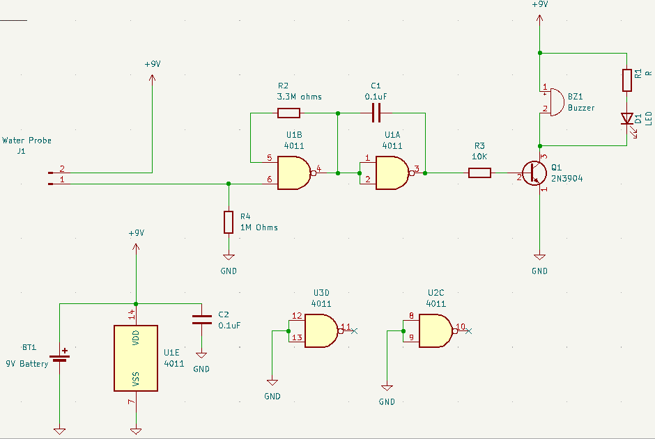
The Schematic
Circuit Explanation
Above, U1B, J1, and R4 form the water level detect circuit. J1 and R4 creates a voltage divider based on the basic resistance of water. Note that the input impedance of a CMOS NAND gate is fairly high. Upon detecting water, pin 6 of U1B goes high. This triggers an astable multivibrator circuit formed by U1B and U1A with a period defined by the values of R2 and C1.
T = 2.2RC
The astable multivibrator output is fed to the base of transistor Q1 which triggers the buzzer BZ1. An indicator LED can be added such as D1 to add visual.
The circuit can be run with a simple 9V battery. This circuit was tested, and it was observed to have a long battery life since CMOS gates have very little current draw especially in idle mode.
Note that the unused inputs of IC1 (CD4011) should have a defined value (either Vcc or GND) to keep the CMOS chip stable.